For PIX6, PIXHAWK, and Mini Pix flight controllers flashed with open-source firmware, how to configure parameters for helicopters?
5.5 Helicopter Setup (Open‑source Firmware 4.3 and above)
Before starting, perform the following steps:
- Disconnect the three wires between the ESC and motor to ensure the motor will not spin when armed.
- Connect the Li‑Po battery for power.
- Connect the flight controller to the computer GCS via USB.
- Open Config/Tuning → Mandatory Hardware → Helicopter Setup (as shown below).
- Note: Control output is only available in Stabilize or Acro mode. Adjustment and testing are not possible in other modes.
5.5.1 Setup Interface Introduction
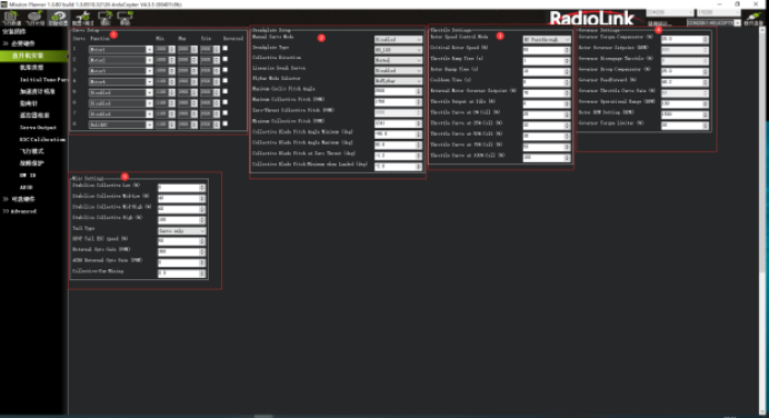
Function Introduction in the Diagram
Channel Function Setup: Assign a function to each PWM output channel.
Swashplate Setup
Throttle Setup
Governor Setup
Mixing Setup
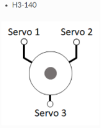
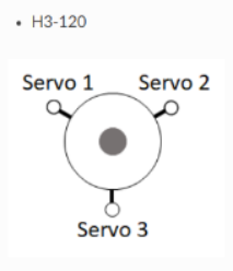
5.2.2 Select Swashplate Type
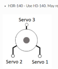
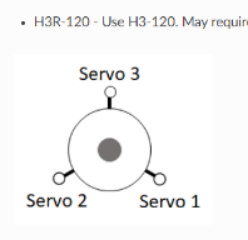
The swashplate type is selected using the H_SW_TYPE parameter. The diagram below labels the servo connection positions for the three 3‑servo swashplate types as Servo 1, Servo 2, and Servo 3. These correspond to the default output functions of Servo Outputs 1 through 3 on the autopilot, intended for use with servos of these swashplate types.
For a single‑rotor helicopter, the servo function assigned to Servo 1 is Motor 33, Servo 2 is Motor 34, and Servo 3 is Motor 35. These assignments are identical to Swashplate 1 on a twin‑rotor helicopter frame. On a twin‑rotor helicopter, Swashplate 2 defaults to Servo Outputs 4, 5, and 6, assigned to Motor 36, Motor 37, and Motor 38, respectively.
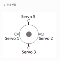
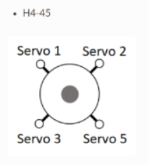
For a 4‑servo swashplate:
On a single‑rotor helicopter frame, the fourth servo (Servo 5) defaults to Servo Output 5 and is assigned Motor 37.
On a twin‑rotor helicopter frame, the fourth servo on Swashplate 1 (Servo 7) defaults to Servo Output 7 and is assigned Motor 39. The fourth servo on Swashplate 2 (Servo 8) defaults to Servo Output 8 and is assigned Motor 40.
H3 Generic: Allows users to configure servo positions and phase angles. Assumes all swashplate ball links are equidistant from the main shaft.
H1 non‑CCPM: Servo 1 = Aileron, Servo 2 = Elevator, Servo 3 = Main Rotor Pitch.
5.5.3 Swashplate Travel Setup
First, adjust the swashplate servos for correct response to transmitter commands
If any servo moves incorrectly, reverse its direction in Figure 1 of Section 5.5.1. Check the box for the corresponding servo to reverse its direction.
Level the swashplate
If adjustment is needed, use the trim values for the corresponding servo in Figure 1 of Section 5.5.1. Make small adjustments until the swashplate is level.
Set swashplate travel limits
In this section, set the travel limit to ±10 degrees.
(1) Install a pitch gauge on the main rotor blades.
(2) Open the Helicopter Setup page in the GCS.
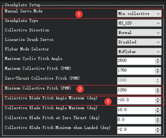
Set ① Manual Servo Mode (shown in the figure below) to Max collective.
Observe the reading on the pitch gauge. Adjust the value at ② until the gauge reads +10 degrees.
Finally, set the value at ③ to 10.
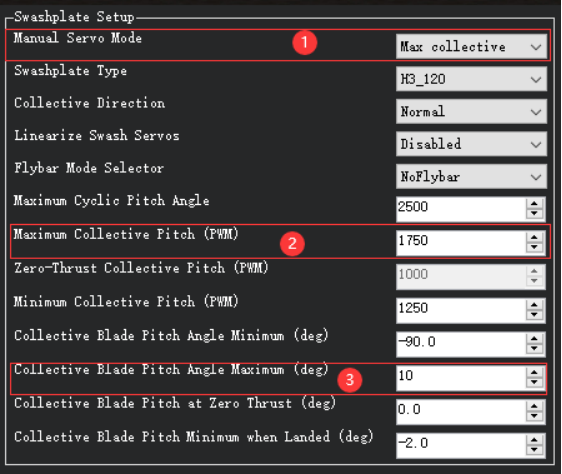
(3) ‑10° Setup. First, set ① Manual Servo Mode (shown in the figure) to Min collective. Check the pitch gauge reading and adjust the value at ② until the gauge reads ‑10 degrees. Finally, set the value at ③ to ‑10.
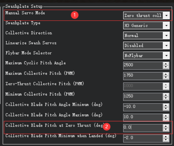
(4) 0° Setup. First, set the value at ① (shown in the figure) to move the swashplate to the zero‑thrust position. Then check whether the pitch gauge reading matches the value at ② (shown in the figure).
(5) The H_COL_LAND_MIN parameter sets the minimum main rotor pitch limit (in degrees) for altitude‑hold modes on the vertical axis. This prevents the autopilot from driving collective pitch too low and causing ground resonance; it also enables landing detection in these modes.
The default H_COL_LAND_MIN setting is ‑2° main rotor blade pitch. This allows aircraft with symmetric blades to descend at a reasonable rate while avoiding excessive negative pitch near the ground.
For asymmetric blades, set this parameter to a pitch angle lower than the zero‑thrust pitch angle. For example, if H_COL_ZERO_THRST is set to ‑3°, set H_COL_LAND_MIN to ‑5°.
5.5.4 Rotor Speed Control Setup
Set RSC mode: Click the dropdown menu at ① in the figure and select the desired mode.
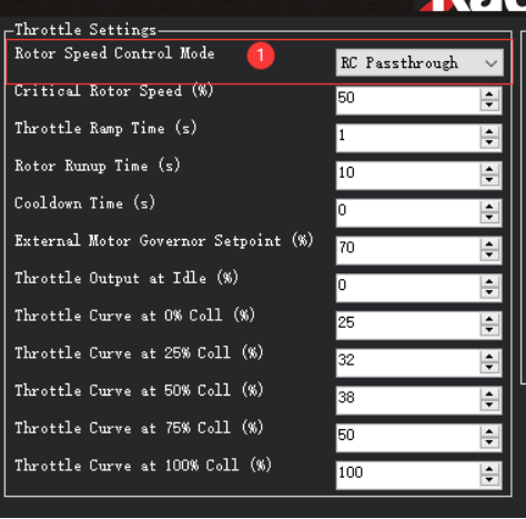
RSC has multiple modes. Brief descriptions of each RSC mode are as follows
(1) RC Passthrough — This mode follows the input from an RC channel assigned for motor interlock (RCx_OPTION = 32). The channel signal must exceed 1200 µs for the heliRSC output to follow the RC input. Otherwise, the heliRSC output will be set to the value of H_RSC_IDLE.
(2) RSC setpoint — For helicopters using an electronic speed controller (ESC) or an external engine governor. The PWM sent to the HeliRSC output is determined by the external motor governor setpoint parameter H_RSC_SETPOINT.
PWM output formula:
PWM output = RSC_SETPOINT × 0.01 × (SERVOx_MAX − SERVOx_MIN) + SERVOx_MIN
where SERVOx is the output assigned to Throttle.
This is the most common mode for electric helicopters using ESC‑built‑in governors.
(3) Throttle curve — Open‑loop control of the HeliRSC servo output. The user must fine‑tune the throttle curve to maintain the desired rotor speed across the flight envelope. The curve is defined as a 5‑point spline via H_RSC_THRCRV_x parameters. It maps collective stick input on the transmitter to HeliRSC servo output.
This mode does not provide constant rotor speed control, but it is typically used to set a feedforward baseline throttle curve for the governor modes below. A properly tuned RSC governor is strongly recommended for stable tuning.
(4) AutoThrottle — Requires a rotor speed sensor. Provides an advanced auto‑throttle governor, mainly for piston and turbine engines. Used when no external RSC governor is available.
Warning: Before using AutoThrottle, the throttle ramp time and throttle curve must be correctly tuned in Throttle Curve mode.
Note: Setting RSC mode to RC Passthrough requires the RC receiver to hold the last value of the motor interlock channel (default: Channel 8). If the receiver loses link with the transmitter and is not configured correctly, the motor will shut down and the helicopter will crash. This also means the pilot must manage throttle during altitude‑hold or autonomous modes, which is difficult and may cause crashes. Strongly discouraged; intended only for highly experienced advanced users.
2. Rotor Speed Curve and Idle Setup
Rotor speed control includes an idle setting and startup/shutdown logic for throttle control.
- H_RSC_IDLE: Throttle output sent to the heliRSC servo after arming but before motor interlock is enabled.
- When motor interlock is enabled, RSC ramps throttle from idle (H_RSC_IDLE) to flight settings (depending on H_RSC_MODE) over H_RSC_RAMP_TIME.
- RSC prevents takeoff in non‑manual throttle and autonomous modes until the timer reaches H_RSC_RUNUP_TIME.
- H_RSC_RUNUP_TIME must be set to the time required for the rotor to reach flight speed; it must be ≥ H_RSC_RAMP_TIME.
- When motor interlock is disabled at flight speed, RSC counts down the same H_RSC_RUNUP_TIME period.
- H_RSC_CRITICAL: Declares rotor speed below critical and resets the spin‑up complete flag. Set it to a percentage corresponding to roughly 3 seconds of run‑up time. Example: 10‑second run‑up → set H_RSC_CRITICAL = 70%.
- For firmware 4.0 and earlier: After declaring low rotor speed, the autopilot can disarm during auto‑landing.
- For firmware 4.1 and later: The autopilot waits H_RSC_RUNUP_TIME before disarming during auto‑landing.
5.5.5 Internal Governor Setup
ArduPilot provides an internal RSC governor (H_RSC_MODE = 4) for applications without an external governor, to maintain a constant head speed.
This mode requires H_RSC_THRCRV_x and H_RSC_GOV_x parameters, plus an RPM sensor to measure head speed.
The governor maintains target rotor speed using:
- A proportional controller with droop compensation
- A feedforward controller using the throttle curve to handle sudden rotor load changes
- A torque compensator that adjusts the reference based on density altitude to keep RPM stable
Governor protection:
- If RPM deviates beyond the governor range for >0.5 seconds, an overspeed/underspeed fault is triggered, and throttle reverts to the throttle curve.
- The governor resets only after disabling motor interlock.
Governor Parameters
- H_RSC_GOV_COMP — Torque compensator: Adjusts the base torque reference to compensate for density altitude changes.
- H_RSC_GOV_DROOP — Droop compensator: Proportional gain for correcting rotor speed error.
- H_RSC_GOV_FF — Feedforward gain: Improves throttle response during sudden rotor load/unload.
- H_RSC_GOV_RANGE — Governor operating range: RPM band around H_RSC_GOV_RPM where the governor is active.
- H_RSC_GOV_RPM — Target main rotor RPM maintained when the governor is engaged.
- H_RSC_GOV_TORQUE — Torque limiter: Adjusts engine torque rise percentage during acceleration to governor speed.
Tuning Steps
- First tune the throttle curve (use H_RSC_MODE = 3). The curve does not need perfect accuracy but must be close enough for safe flight.
- If the RPM sensor fails, control reverts to the throttle curve. A poorly tuned curve will cause crashes.
- For ICE/turbine helicopters: Set H_RSC_IDLE so the engine starts and runs without engaging the clutch or turning the main rotor.
- After tuning the curve, set H_RSC_MODE = 4 to enable the governor.
Governor Tuning
- Start with the governor targeting the RPM of the tuned throttle curve to minimize torque compensator use.
- Tune feedforward first: Increase gain if rotor speed drops significantly under collective load.
- Tune droop compensation for precise RPM holding: Higher values react faster to load changes but risk surge. Tune aggressively without surge or RPM spikes.
- Tune torque compensator (H_RSC_GOV_COMP) slowly: Increase by 1% if RPM deviates >2–5 RPM. Avoid large steps; excessive gain causes throttle oscillation.
- Torque limiter (H_RSC_GOV_TORQUE): Only adjust if target RPM is higher than the curve RPM. Increase by 5% if the governor fails to engage on acceleration; stop if overspeed faults occur.